Simbell is a hardware system to connect bells in a belfry or on a dumbbell to a computer located in the ringing room.
There are two main active components to the system.
TRANSMITTER
The transmitter is located in the belfry and detects the position of the bell wheel by sensing a reflective strip as the bell passes its lowest point.
RECEIVER
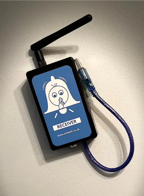
The receiver is connected to the computer in the ringing chamber and collects the information from the transmitter, turning it into signals that the software you are using can understand.
Typical simplified scenario..
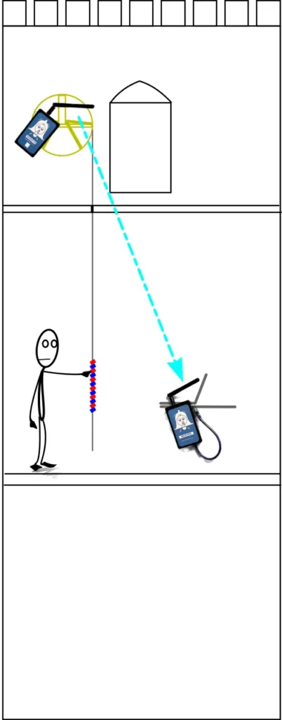
In this scenario, we have a belfry and ringing room with a single floor between them, a transmitter is placed on the frame next to the wheel in the belfry and the receiver is plugged into a laptop in the ringing room, the transmitter can be powered from a mains adapter or battery and the receiver is powered from the USB Port of the laptop.
The location of the ringing room on the groundfloor only adds a floor between the the tranmitter and receiver and experience shows that the cast majority of cases have no problem with this arrangement.
We have towers with a distance of 35′ to the floor of a clock room, another 10′ to the floor of the belfry and then the frame above that work without a problem. If you have concerns then contact me and let me have details and I can provide some insight into issues that you may encounter.
Please note that wireless signals do not travel through floors of lead lined belfry’s, we have had a few of these and these require a wired solution.
Installation
Installation of the system is very simple. I have produced some installation videos on how to carry out a complete installation on 6 bells, including the setup of the most common ringing software, as well as setting up a temporary or “popup” installation on a single bell for a training session which takes just a few minutes.
Every system comes with a manual which you can also download the latest version as a PDF from here.
- Full Installation
This video shows step by step the installation of a complete Simbell System in a 6 Bell Tower, from checking the transmitters are working, to setting up Virtual Belfry and Abel with the correct delay times for the striking of each bell.
This is a real installation in our local tower which has had a refurbishment of the frame completed.
This is a long(ish) video, but we think it is important to get as much information about an installation over, but if you want to skip to a particular part then the timings are below:
00:00 Introduction
01:45 Checking the system before installation
06:00 Setting up the Receiver and Transmitters and Laptop
19:04 Positioning Transmitters on the Frame
21:50 Power Cabling and Connectors
25:23 A look at the completed wiring and positions
27:30 Installing the reflectors on the wheels
28:48 Aerial Positioning
30:38 Setup of the Delay Timing on Virtual Belfry and Abel
38:25 Final Round up and hints
- "Pop Up" Installation
In this video we look at how with Simbell, in just a few minutes you can set up the simulator hardware in a tower to use for teaching or practice.
In this video were are using, one transmitter, one receiver, a battery pack, a laptop (and a bike inner tube to tie the clapper).
- Transmitter Positioning
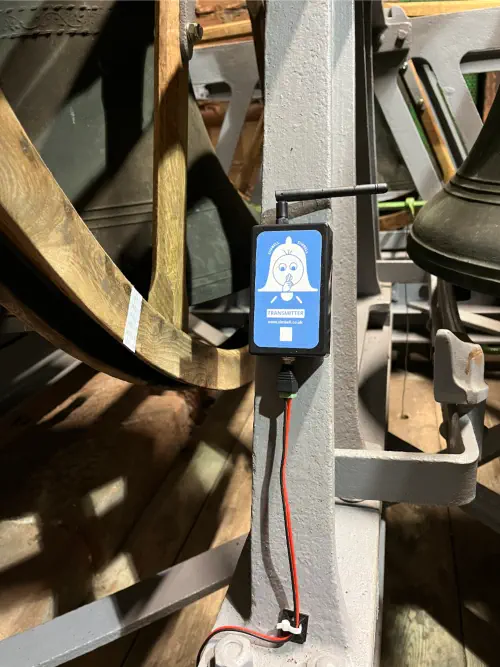
The transmitter is attached to a suitable part of the frame where it can see the shroud of the wheel where a self-adhesive reflective strip can be detected by the transmitters sensor.
In this picture you can see the transmitter has been mounted on an upright frame member (in this case with magnets) and the reflective strip can be seen on the wheel shroud.
The aerial on the transmitter has been placed so that the signal is vertical and outside the frame for the best reception in the ringing room below.
ENSURE THAT THE ANTENNA IS AT 90 DEGREES TO THE BODY OF THE UNIT AS SHOWN IN THE PHOTO – IF IT IS STRAIGHT THEN THIS CAN CAUSE MISSED SIGNALS AND LOW TRANSMISSION POWER